
Visualization and Simulation of Robotic/UFS*
Testing System: Registration of Lumbar FSU**
Stephanie Coquia, Todd C. Doehring, M.S., Lars G. Gilbertson, Ph.D.
Testing System: Registration of Lumbar FSU**
Musculoskeletal Research Center
Department of Orthopaedic Surgery
University of Pittsburgh Medical Center, PA
* Universal Force-Moment Sensor
** Functional Spinal Unit
** Functional Spinal Unit
Introduction
A functional spinal unit (FSU) is the smallest segment of the spine that exhibits the biomechanical characteristics of the entire spine. One FSU consists of two vertebrae, the intervertebral disc, and the interconnecting ligaments. The Spine Research Group has previously performed experiments on the flexion/extension characteristics of the lumbar FSU using the robotic/UFS testing system [1]. However, registration of the specimen with respect to the robot was not done. Registration of the specimen with respect to the robot coordinate system is important for knowing exactly where the specimen and its components are in relation to the robot. Accurate specimen registration will allow calculation of the load-displacement response of individual FSU component structures. The elongation of the various ligaments can be determined and the deformation of the disc can also be estimated. Registration will also allow determination of the facet contact area.
Objective
The objective of my summer project was to develop an experimental and analytical method to register specimen geometry (FSU) with respect to the robotic end-effector and UFS coordinate systems. To validate the method, a simple physical model was developed and tested.
Methods and Materials
Fabrication of Physical Model of FSU
For this "proof of concept" study, a simple physical model of an FSU was first constructed (Figure 1). Starting from two sawbone vertebrae, two layers of mousepad were used to represent the intervertebral disc. Cable ties were used to model ligaments and registration blocks were added. Dice blanks kindly provided by Midwest Game Supply Company (Kearney, MO) were used as registration blocks. The entire FSU was connected by a nylon bungee cord.
Figure 1. Schematic of physical model (illustration by Maura George, 2000).
The next part of the project involved creating a virtual model of the FSU. Normally, CT scans of the specimen would be used to reconstruct the geometry of the vertebrae on the computer. In the current study, an existing computer model vertebra was modified to match the geometry of each of the vertebrae of the physical model. To modify the existing geometry, the geometry of each sawbone vertebra had to be measured first. Using MicroscribeTM, a 3-D geometry measurement device, points on the surfaces of each sawbone vertebra were digitized. The coordinates of these points were imported into a solid modeling software program (Caligari TrueSpaceTM). Each pointŐs coordinates were represented as a 1 mm sphere to show the digitized point with respect to the surface of the model. Using editing options in TrueSpaceTM, the mesh of the existing computer model was modified to best fit the set of spheres. This entire procedure was done for each vertebra. A similar process was followed to add the registration blocks to the computer models.
The addition of registration blocks served several purposes. By setting up a local coordinate system for each block, the two vertebrae in the virtual model were aligned. In addition, these local coordinate systems were used to relate the specimen to the robot end-effector and UFS coordinate systems through transformation matrices.
Establishment of local coordinate systems required digitization of the anterior, inferior, and lateral faces of the registration blocks followed by the use of a MathematicaTM program called "Planefitter.nb" (developed by James Pfaeffle, Ph.D. and the Upper Extremity Group at the MSRC). This program calculated a local coordinate system on each block with its origin at the intersection of the anterior, inferior, and lateral faces of the block. In addition, the program computed the direction cosine matrix and the x, y, and z coordinates of the origin of the local coordinate system on each block with respect to the Microscribe coordinate system.
Using these matrices and coordinates, a MatlabTM program was written to calculate the homogeneous transformation matrix of the top block with respect to the bottom block as well as the Euler angles. These data were input into TrueSpaceTM to align the top vertebra+block model with respect to the bottom vertebra+block as shown below in Figure 2.
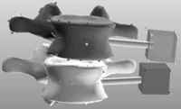
Figure 2. Completed computer model of two vertebrae in FSU.
Once the path was found, a sequential cutting study was performed to determine the load-bearing contributions of the various elements of the physical model of the FSU during flexion/extension. The posterior cable tie was cut first, representing the removal of the supraspinous and interspinous ligaments. The anterior cable tie was cut next, representing the removal of the anterior longitudinal ligament. Then, the intervertebral disc and the bungee cable were removed, leaving only the two sawbone vertebrae with interaction through the facet joints only. Finally, as an experimental check to assure that no resistive load was measured when there was no contact of FSU component structures, the inferior vertebra was removed, leaving just the superior vertebra mounted.
The transformations between specimen coordinate systems and the robot end-effector and UFS coordinate systems were calculated using the "Planefitter.nb" program.
Results
The completed computer model of the FSU is shown in Figure 2. Force-moment contributions of individual FSU structures are shown in Figures 3 and 4.
Figure 3. The resistive flexion-extension moment of the FSU and cable ties as a function of flexion/extension rotation.
Figure 4. The superior forces of the FSU and cable ties as a function of flexion/extension rotation.
Discussion
Previous Spine Research Group experiments of lumbar FSUs did not include specimen registration in Robotic/UFS tests. The Upper Extremity Group and the ACL Group of the MSRC have been using registration techniques to determine, among other things, the force-moment contributions of ligaments during physiological motion. My summer project involved developing a registration technique for lumbar FSU testing.
As shown by Figure 3, the posterior cable tie contributed nearly all of the FSU resistive moment during flexion. The anterior cable tie was a major contributor to the resistive moment during extension. Figure 4 supports these findings in that the resistive moments are proportional to the forces in the FSU components.
Future Directions
In the future, data taken from experimental tests on the robot will be used to run simulations on computer. Once the robotic/UFS simulation is updated to include specimen geometry and its properties, these simulations will allow for the determination of the force-elongation characteristics of FSU ligaments during experimental tests.
References
1.) Gilbertson LG, Doehring TC, Moon S-H et al. "Delineation of in-vitro lumbar spine kinetics using a robotic/UFS testing system with hybrid control." J. Biomechanical Engineering (In Review) 2000.
Acknowledgments
This project could not have been accomplished without the kind assistance of Ms. Linda Sohm of the Midwest Game Supply Company, who graciously supplied us with the dice blanks used as registration blocks. IŐd like to thank Todd Doehring, M.S., for putting up with me these past three months. Special thanks to Dr. Gilbertson for all his guidance. IŐd also like to thank Kitty Stabile, B.S., and Mary Gabriel, B.S., for their help in teaching me the techniques of digitization. Thanks to Dr. Debski, Dr. Woo, the Musculoskeletal Research Center, and the Bioengineering Department for giving me the opportunity to work here. Lastly, I want to thank the summer students for their friendship and support.