
Computer-Aided Interosseous Ligament Reconstruction Planning
Fiona Bullen, J. Pfaeffle MD/PhD, K. Stabile BS, M. Gabriel BS, M. Tomaino MD, K. Fischer PhD
Musculoskeletal Research Center
Department of Orthopaedic Surgery
University of Pittsburgh Medical Center, PA
Introduction
The interosseous ligament (IOL) is a very important structure in the forearm, which runs between the proximal radius and the distal ulna. It functions to transfer load between the two bones and stabilize the distal and proximal radioulnar joints [1]. The IOL can be damaged or torn during high impact compressive loading applied axially at the distal end of the forearm. This usually occurs from a high-energy fall, in which a person tries to catch himself/herself with an outstretched hand.
This injury usually results in a shattered radial head, damage to the IOL, and rupture of the triangular fibro-cartilage complex. This will cause the injured party to suffer from pain, loss of motion, and joint degradation [2]. Up to this point, treatment of this injury is incomplete and most clinicians have not attempted to repair or reconstruct the IOL. However, because other treatments have been relatively unsuccessful, interest in IOL reconstruction has increased. Little data on IOL geometry is available and reconstruction attempts have had limited success. The objective of my study was to geometrically investigate IOL reconstruction variables using computer modeling.
Methods and Materials
|
Ten dissected cadaver forearms were CT scanned in neutral rotation. Using in-house computer software, each CT slice of the radius, ulna, and IOL were digitized. These text files, which represented separate curves, were parameterized and two surface patches were created. These patches (ibl files) were then. Imported into the CAD program Pro/ENGINEER (PTC, Waltham MA). The radius and ulna were created as solid structures, and the IOL was simply created from a set of curves. Of the ten specimens studied, five had the full radial and ulnar bone geometry. For these five specimens, the total lengths of the bones were measured. The lengths from the distal articular surface of the ulna to the ulnar mid-insertion site, and distal articular surface of the radius at the carpus, to the radial mid-insertion site were also measured. Specific locations are shown in Figure 1. Also using these five specimens, the angle of the IOL was measured. This was accomplished by drawing a straight axis down the length of the bone and measuring the angle between the longitudinal axis and the axis of the IOL. This process was repeated ten times for each bone of each specimen, to decrease the chance of human error. Each specimen angle used was the average of the ten angles found.
Using all ten specimens, the length of the IOL between the radial and ulnar insertion sites was measured. In order to estimate graft length, the length of the IOL plus the distances across the bones were measured. For this, two different bone widths were measured. One width was measured along the axis of the IOL (collinear) and one transverse to the long axis of the bone (Figure 2). The minimum (posterior/anterior) diameter of the bones was also measured. This will give an idea of what allowable size hole could be drilled for graft tunnels. After measurements were taken, reconstructions were modeled geometrically in Pro/ENGINEER. Virtual holes were drilled into the bones and solid cylinders were fitted into the bones acting as grafts. |
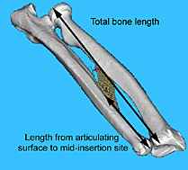 Figure 1 Display of total bone length and articulating surface to mid-insertion site measurements
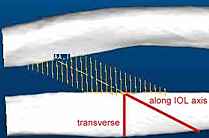 Figure 2 Display of transverse and collinear distances across bone
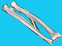 Figure 3 5mm diameter hole with 4.95 mm diameter graft
|
Results
A total of ten specimens were used for this study, though only five of these had their bone geometry completely CT scanned. Measurements using only five specimens are indicated in the tables by (*) and all others are based on ten specimens. Table 1 displays the total length of the radius and ulna and the percent of the total length from the specific distal surface points (shown in Figure 1) to the mid-insertion site. The length data of the insertion sites on the bones is also included. This data shows that there is substantial variability in insertion site length.
| Radius | Ulna | |
| Total bone length* | 244.1Ý 13.5 mm | 267.3Ý 14.3 mm |
| Length from surface to mid-insertion as a % of total bone length* | 56.5 Ý 2.7 % | 34.9 Ý 3.2 % |
| Insertion length | 27.2 Ý 4.8 mm | 44.2 Ý 7.9 mm |
Table 1 IOL Location information
* n = 5
* n = 5
| Total IOL& IOL axis bone length | 113.4 Ý 16.0 mm |
| Total IOL& transverse bone length | 74.9 Ý 8.0 mm |
| Angle of IOL from long axis of bones* | 24.4 Ý 2.3 degrees |
Table 2 IOL angle and graft length information
* n = 5
* n = 5
| radius | ulna | |
| PA bone diameters | 12.0Ý .9 mm | 11.7Ý 1.1 mm |
Table 3 Bone diameter information
Discussion
One of the most important parts of my study was determining a way to locate the IOL by correlating its insertion sites to the length of the radius and ulna. It is significant because the IOL is under a lot of muscle and soft tissue and does not appear on an X-ray. The main purpose of the percentage data was to aid clinicians in predicting insertion sites on standard PA X-ray films.
The purpose of measuring the IOL length and length of tunnels through the bone, was to estimate the length of grafts needed for reconstruction. I found that drilling virtual holes transverse to the long axis of the bones instead of along the axis of the IOL, would decrease the length of graft needed. Another advantage to drilling holes transversely would be that less bone would be lost and therefore less chance of the bones breaking. However with transverse tunnels, it may be more difficult to thread the graft through the holes. Also less bony contact with the graft may cause it to loosen more quickly. The angles obtained for the IOL were fairly consistent from specimen to specimen. If tunnels were drilled collinearly then the information on the IOL angles could be very helpful to a surgeon.
The posterior/anterior diameters of the bones were measured in order to estimate what size hole would be suitable, so as to minimize risk of bone fracture. The mean value of the diameters was about twelve millimeters. Stress concentration calculations need to be performed in order to estimate what tunnel diameter would be acceptable. However, certain graft types are clearly too large to use because of their size. A person with small arms, such as a petite woman would require smaller tunnels.
Two tunneling techniques being considered are the single tunnel reconstruction and the double tunnel reconstruction. The single tunnel method would be clinically much easier to perform, but previous stress/strain work from our Upper Extremity group suggests that the double tunnel method could possibly behave more like the native IOL. This theory will have to be investigated by computational modeling with varied forearm rotation and a compressive axial load.
References
1.) Birkbeck, D. P., J. M. Failla, et al. (1997). Journal of Hand Surgery - American Volume, 22(6): 975-80.
2.) Hotchkiss, R. N. (1994). Hand Clinics, 10 No. 3: 391-398.
Acknowledgments
Special thanks to Dr. Fischer for advising my project. I am extremely grateful for the help I received from the Upper Extremity group: Jamie Pfaeffle, Kitty Stabile, Mary Gabriel, and Damion Shelton. Also thanks to all the people in the MSRC!